
SMX-RNS20 User Guide
Preface
Section titled “Preface”Purpose of the Document
Section titled “Purpose of the Document”This document contains information about the following topics;
-
SMX-RNS20 Product Information
-
SMX-RNS20 Setup
-
Use of SMX-RNS20
-
SMX-N1559 (Optional)
-
SMX-RS001 (Optional)
Required Level of Knowledge
Section titled “Required Level of Knowledge”In order to fully understand and apply this document, it is necessary to have knowledge of IT, Automation and Electricity.
Contents
Product Description and Certificates
Section titled “Product Description and Certificates”The SMX-RNS20 module is an Industrial Remote Connection device that provides the infrastructure needed for Industry 4.0, allowing you to connect to your remote field devices under high security measures and collect data from your devices.
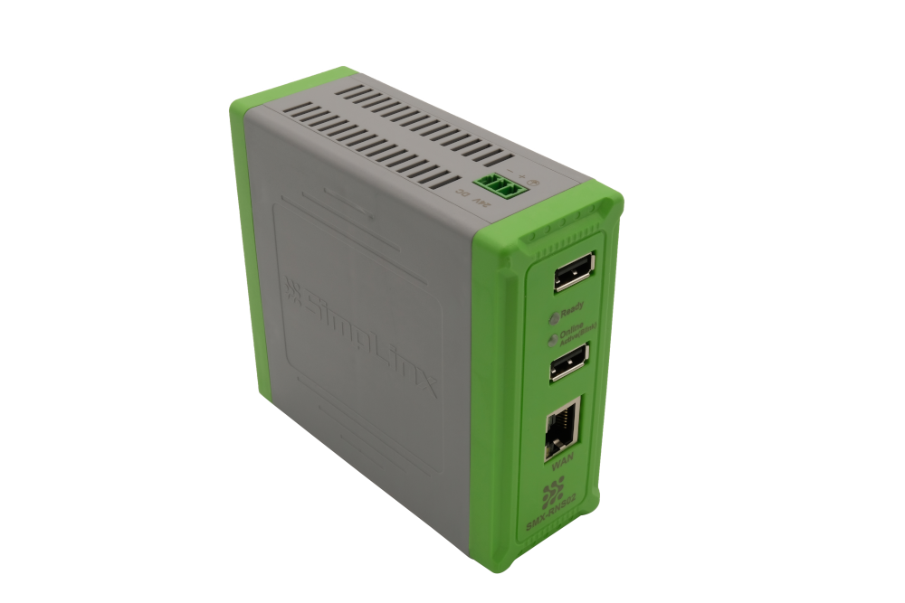
| Processor | BCM2837 1.2 GHz Quad Core |
|---|---|
| Ram | 1 GB LPDDR2 400MHz |
| eMMC | 4 GB |
| Storage | 2 GB |
Properties
Section titled “Properties”-
High degree of robustness.
-
The SMX-RNS20 module is approved for indoor use only.
-
Compact design.
-
Ethernet and USB interfaces.
Security
Section titled “Security”-
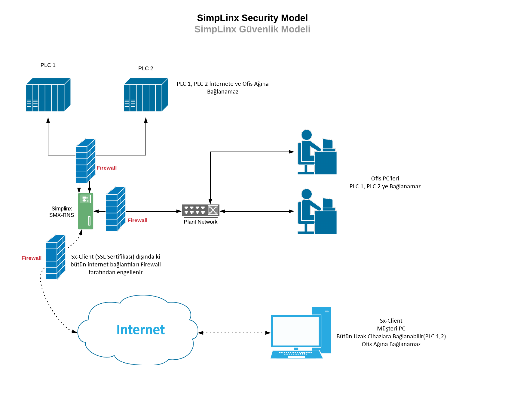
Integrated Firewall.
-
Certificate-based protection (4096 Bit Certificate / SHA256)
-
All traffic to the module without being encrypted with the certificate is blocked by the Firewall.
-
Access to the module from the office network where the SMX-RNS20 module is located is blocked by the Firewall.
-
Access of devices connected to the SMX-RNS20 module to the office network is blocked by the Firewall.
Approvals / CE
Section titled “Approvals / CE”The SMX-RNS20 module has received approval from the CE standards tests listed below.
Electromagnetic Compatibility
-
EN 55032:2015 Emissions (Diffusion) Tests
-
EN 55024:2010/A1:2016 Immunity Tests
-
EN 61000-4-2: 2009
-
EN 61000-4-3: 2006/A2:2010
-
EN 61000-4-4: 2012
-
EN 61000-4-5: 2014/A1:2017
-
EN 61000-4-6: 2014/AC:2015
Electrical Security
- EN 62368-1:2014+A11:2017
Physical Properties and Drawings
Section titled “Physical Properties and Drawings”| Power Supply | 24 V DC | Minimum = 15V DC Maximum = 30 VDC |
|---|---|---|
| Power Consumption | 200mA | |
| Connection Slots | 2xUSB 2.0 | |
| 1xRj54 WAN | 100 Mb/s | |
| 2xRj45 LAN | 100 Mb/s | |
| Box | DIN Rail Mounted | |
| Temperature | 0 oC to 70 oC | Work |
| -40 oC to 85 oC | Storage | |
| Dimensions (mm) | Width : 42 Height : 101 Depth : 114 | |
| Weight (Kg) | 0.202 |
Drawings
Section titled “Drawings”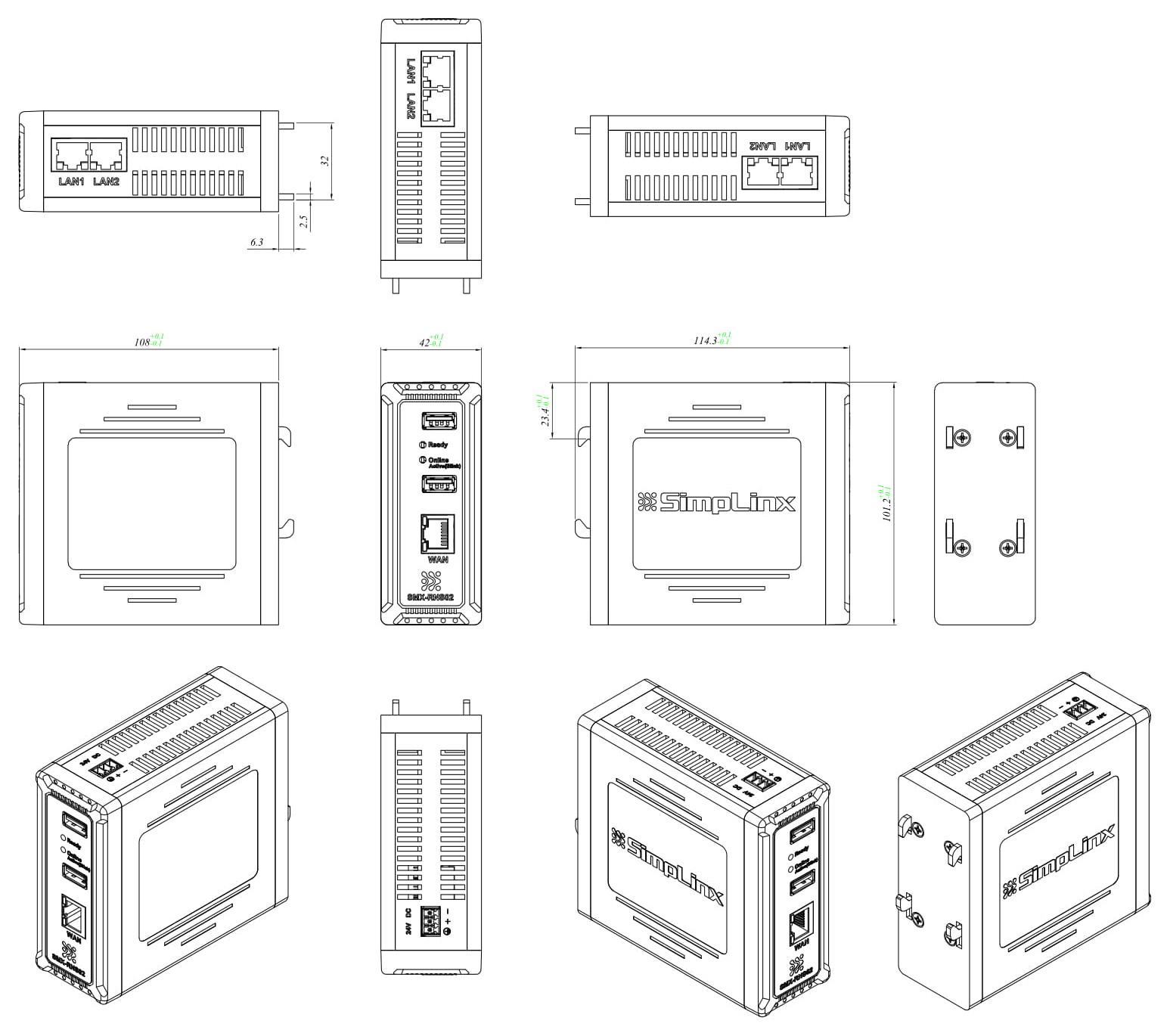
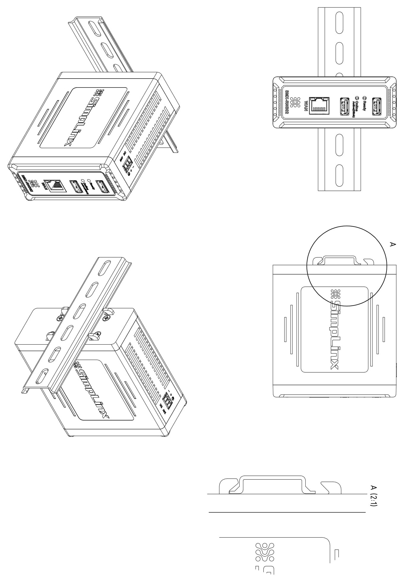
The SMX-RNS20 module can be mounted to DIN rail. It is recommended to be mounted vertically to increase the performance of the device and to provide space advantage.
Mounting
Section titled “Mounting”-
Bring the top of the device to the top edge of the standard profile rail and place the device on the rail track.
-
Push the device towards the standard profile rail. You will hear the device sitting in place with the click sound.
Removing
Section titled “Removing”-
With the help of a screwdriver, pull down the locking spring from the bottom of the device.
-
Separate the screwdriver from the rail line without separating it from its position, pulling the clight towards yourself.
Electrical Connection
Section titled “Electrical Connection”The SMX-RNS20 module has 1 terminal group, called X1. On the hardware versions described by this guide it carries 3 terminals, as follows;
| X1 | ||
|---|---|---|
| + | - | GND |
After you have completed the physical installation of your device, you can run your device by connecting the device (+), (-), and GND terminals to the appropriate terminals at the power supply output.
Schema
Section titled “Schema”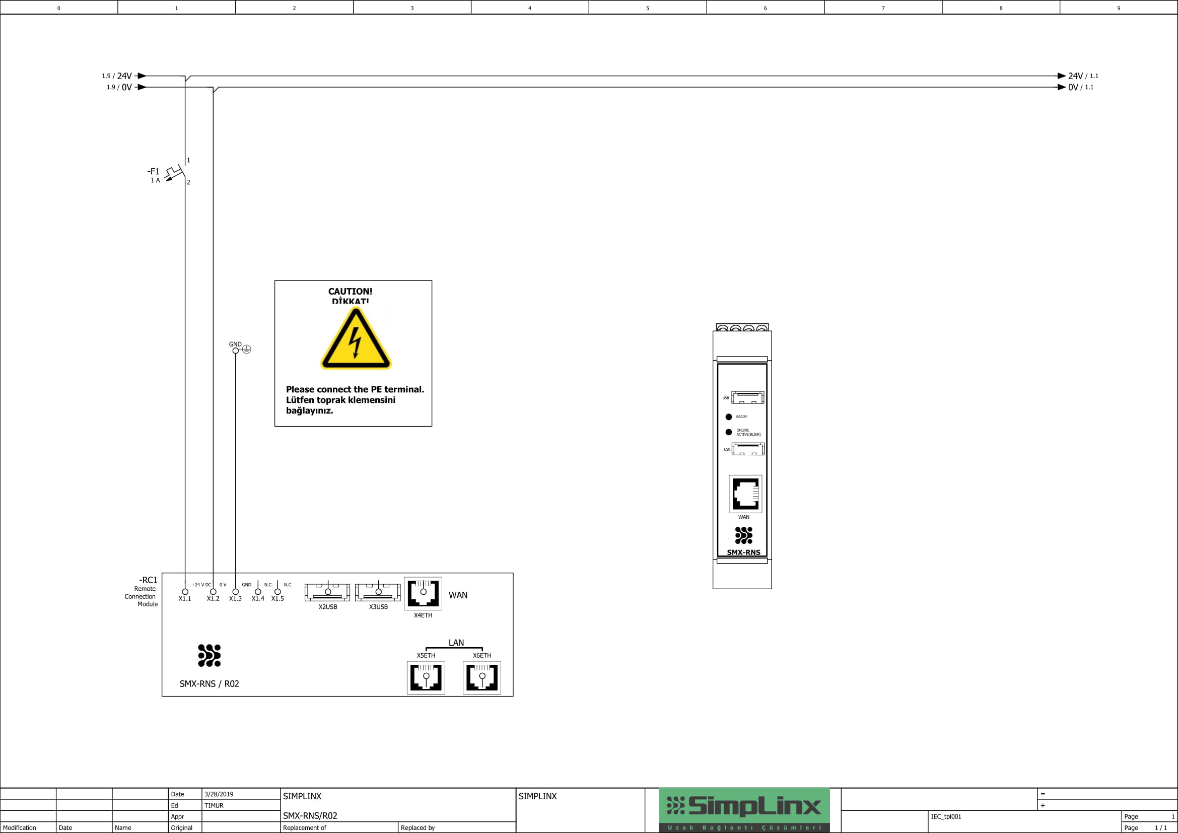
Device Connections
Section titled “Device Connections”Ethernet Devices
Section titled “Ethernet Devices”To connect your Ethernet devices to the SMX-RNS20 module, you must set up an IP in the IP range that you have given to the SMX-RNS20 module.
- Example
If your SMX-RNS20 module is in the following settings
-
IP: 192.168.168.254
-
Subnet Mask: 255.255.255.0
-
IP (PC): 192.168.168.250
In this case, you must provide an IP address for your devices in the range of [192.168.168.1 – 192.168.168.249] and [192.168.168.251 - 192.168.168.253]
After you adjust your field device’s IP addresses, you can connect your devices to 2 Ethernet ports on the SMX-RNS20. You do not need to make any adjustments other than IP address.
Use of Ethernet Ports as a Switch
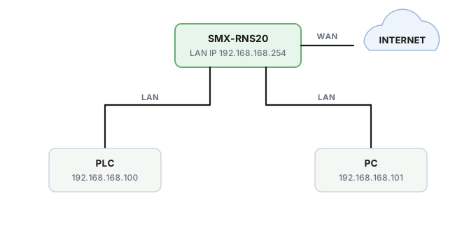
Section titled “Use of Ethernet Ports as a Switch”With the “KSZ8895” Microchip used in the SMX-RNS20 module, your Ethernet devices that you connect to module can communicate with each other.
- Device 1
- IP: 192.168.168.100
- Device 2
- IP: 192.168.168.101
- SMX-RNS20
- IP: 192.168.168.254
If your devices and module are set up as above and connections have been made (IP addresses are used as examples) these connections are possible;
-
Device 1 to Device 2
-
Device 2 to Device 1
Also If you connect to the SMX-RNS20 module by using Wi-Fi as AP than you can access to Device 1 and Device 2.
Switch Chipset Features
| Chipset | KSZ8895 |
|---|---|
| Macs | 5 |
| Interface | MII/RMII |
| VLAN Support | Yes (up to 128 Pieces) |
| Programmable Speed Limitation | Yes |
| Static Mac | Yes (Up to 32 Admissions) |
| RSTP Support | Yes |
| Maximum Packet Size | 2000 Bytes |
| Advanced Features |
|
USB Devices
Section titled “USB Devices”The SMX-RNS20 module has 2 USB slots. You can plug storage devices, SMX-N1559 Wi-Fi module or SMX-RS001 (USB to RS-232) converter. You can increase your number of slots by using an intermediate device, such as a USB Hub.
| Usb | 2.0 |
|---|---|
| Type | A |
| Total Maximum Output Current | 500 mA |
For more information about the SMX-N1559 and SMX-RS001 devices, see the relevant documentation.
Registering SMX-RNS20
Section titled “Registering SMX-RNS20”The “Welcome” screen will open after login in to the system. The screen has two parts. The page structure is in the form of menu on the left and page content on the right.
In order to use the SMX-RNS20 device, the device must be registered first.
Each device has a “Register Info” card. This card has a serial number and registration password. For example,
Register Info
| Model | SMX-RNS20 |
|---|---|
| Serial No. | SRX-XXXXX-XXXXX |
| Password | XXXXX-XXXXX-XXXXX |
-
From the Left Menu, go to the “SX-Node”--->“SX-Node - List” page.
-
Your existing devices are listed in the Table in the Page. If you’re logging into the system for the first time, the list will be empty.
-
Press the icon from Toolbar to +. You will be redirected to the “Add New Device” page.
-
Enter all information by using the “Register Info” card, complete and error-free.
-
Press the Save button.
-
If all information is correct, the device will be registered & displayed in the list.
Preparing SMX-RNS20
Section titled “Preparing SMX-RNS20”WARNING: Don’t energize your device until you get to the relevant step.
Internet Connection Options
Section titled “Internet Connection Options”The Internet can be supplied in 3 different ways to the SMX-RNS20 device.
- WAN port
- Plug the ethernet cable with an Internet connection into your device’s WAN port. DHCP or IP settings will be made in the next steps.
- Phone USB Connection
-
Plug your iPhone or Android phone into your device’s USB port with a charging/data cable.
-
Turn on mobile access from phone settings.
-
After energizing your device and the “Ready LED” is ON, you may need to turn the mobile access setting OFF and ON on your phone.
- Wi-Fi Connection
- This option requires the SMX-N1559 module. See “Installation of the SMX-N1559 USB WiFi Module”section.
Device LEDs and Meanings
Section titled “Device LEDs and Meanings”The front cover of the SMX-RNS20 module has 2 LEDs. These are, respectively from the top;
- Ready LED (Ready LED)
-
OFF: It is OFF when the device is first energized.
-
ON: When the device is booted and ready, this LED lights up and remains in this state.
- Online LED
-
OFF: No Internet connection
-
ON : Internet connection ready
-
BLINK: There is currently an active remote connection
Installation of SMX-N1559 USB Wi-Fi Module (Optional)
Section titled “Installation of SMX-N1559 USB Wi-Fi Module (Optional)”-
Place and tighten the antenna if it is un-mounted.
-
Plug the USB Wi-Fi module into an empty USB slot on the SMX-RNS20.
-
Your SMX-N1559 module is ready for use
Ethernet Connection with PC (Service IP) (Optional)
Section titled “Ethernet Connection with PC (Service IP) (Optional)”There are three methods to access the device settings.
-
Connection over Wi-Fi
-
Physical connection from the service port with Ethernet Cable
-
After a remote connection is made, by accessing the web interface
If you have a Wi-Fi module and want to make settings over Wi-Fi, you can skip this step.
-
Connect one end of the Ethernet Cable to the SMX-RNS20 LAN port (one of the 2 ports at the bottom), and the other end to your PC’s Ethernet port.
-
Go to Ethernet Adapter settings on your PC
-
Double-press on your adapter to go to the detail page
-
Press the Properties button
-
Double-press**” Internet Protocol Version 4 (TCP/IPv4)**” option
-
Select “Manual IP Adjustment” from the page that opens and enter the following information
-
IP : 192.168.169.100
-
Subnet Mask: 255.255.255.0
- Close by confirming changes
Energizing your device
Section titled “Energizing your device”Turn on the power supply or adapter to which the SMX-RNS20 is connected. Make sure that your USB or Ethernet devices that you want to make a remote connection are also turned on.
-
When given the first energy, the “Ready LED” will light up off. About 30 seconds later “Ready LED” will switch to ON position.
-
If the Internet connection is ready, the “Online LED” will turn ON after a short while.
-
If you are trying to provide internet to your device by phone you may need to turn the mobile access setting off and on after the “Ready LED” lights up.
-
If you want to use the IP option manually from WAN or if you want to provide internet with Wi-Fi, your device will connect to the internet after making your settings in the next section.
Making Basic Settings
Section titled “Making Basic Settings”If the device settings will be accessed with the SMX-N1559 Wi-Fi module;
-
View the Wi-Fi networks around you with the Network Icon at the Bottom Right on your PC.
-
The SMX-RNS20 device will be broadcasting Wi-Fi with serial code.
-
From the list, select the network in the format “SRX-XXXXX-XXXXX” that matches your device’s serial number and press “Connect”
-
Enter wifi password
If you have a wired or Wi-Fi connection ready;
-
Open your browser
-
On the Address bar, enter ” http://192.168.169.254:3000” and press ENTER
-
The login screen will open for the SimpLinx device settings.
-
Enter your password and press ENTER
-
Enter the required internet settings from the “WAN” and “Wireless Settings” pages.
-
Go to the “LAN Settings” page.
-
In order to connect to your field devices, your Ethernet field devices and SMX-RNS20 device must be on the same IP network. Enter the settings correctly.
-
Example 1 (Predefined)
-
IP: 192.168.168.254
-
Subnet Mask: 255.255.255.0
-
IP (PC): 192.168.168.250
-
In this case, you can use all IP addresses in the range of [192.168.168.1 - 192.168.168.249 ] and [192.168.168.251 - 192.168.168.253] for field devices.
- Example 2
-
IP: 192.168.0.1
-
Subnet Mask: 255.255.255.0
-
IP (PC): 192.168.0.2
-
In this case, you can use all IP addresses in the range [192.168.0.3 - 192.168.0.254] for your field devices.
- Example 3
-
IP: 10.0.0.1
-
Subnet Mask: 255.255.255.0
-
IP (PC): 10.0.0.2
-
In this case, you can use all IP addresses in the range [10.0.0.3 - 10.0.0.254] for your field devices.
How to Get Device Status via Communication?
Section titled “How to Get Device Status via Communication?”You can get the device status in 2 different ways by communication. These are respectively
- TCP Socket
- Modbus TCP
8.1 TCP Socket
Section titled “8.1 TCP Socket”By connecting to the TCP server running on the port number “3200” on the device, you can get the device status as shown below
“STATUS;<SERIAL_NO>;<1 OR 0>;<ONLINE_ OR OFFLINE>“
8.2 Modbus TCP
Section titled “8.2 Modbus TCP”You can get the device status by connecting to the Modbus Server running on port number “5020” of the device. (Port 502 on the device belongs to SX-IO’s own Modbus server, described under SX-IO.) Device information is sent over Modbus as follows.
Holding Register
40001-40008: Serial No (16 Byte)
40009: EMPTY
40010: Status / 10:Offline, 11:Online
Web Interface
Section titled “Web Interface”LAN Settings Page
Section titled “LAN Settings Page”On the LAN Settings page, you can define the IP address, network mask and the IP address of your PC when you make a remote connection. The network mask value you have entered will determine the IP range of your devices which you will connect to your SMX-RNS20 module.
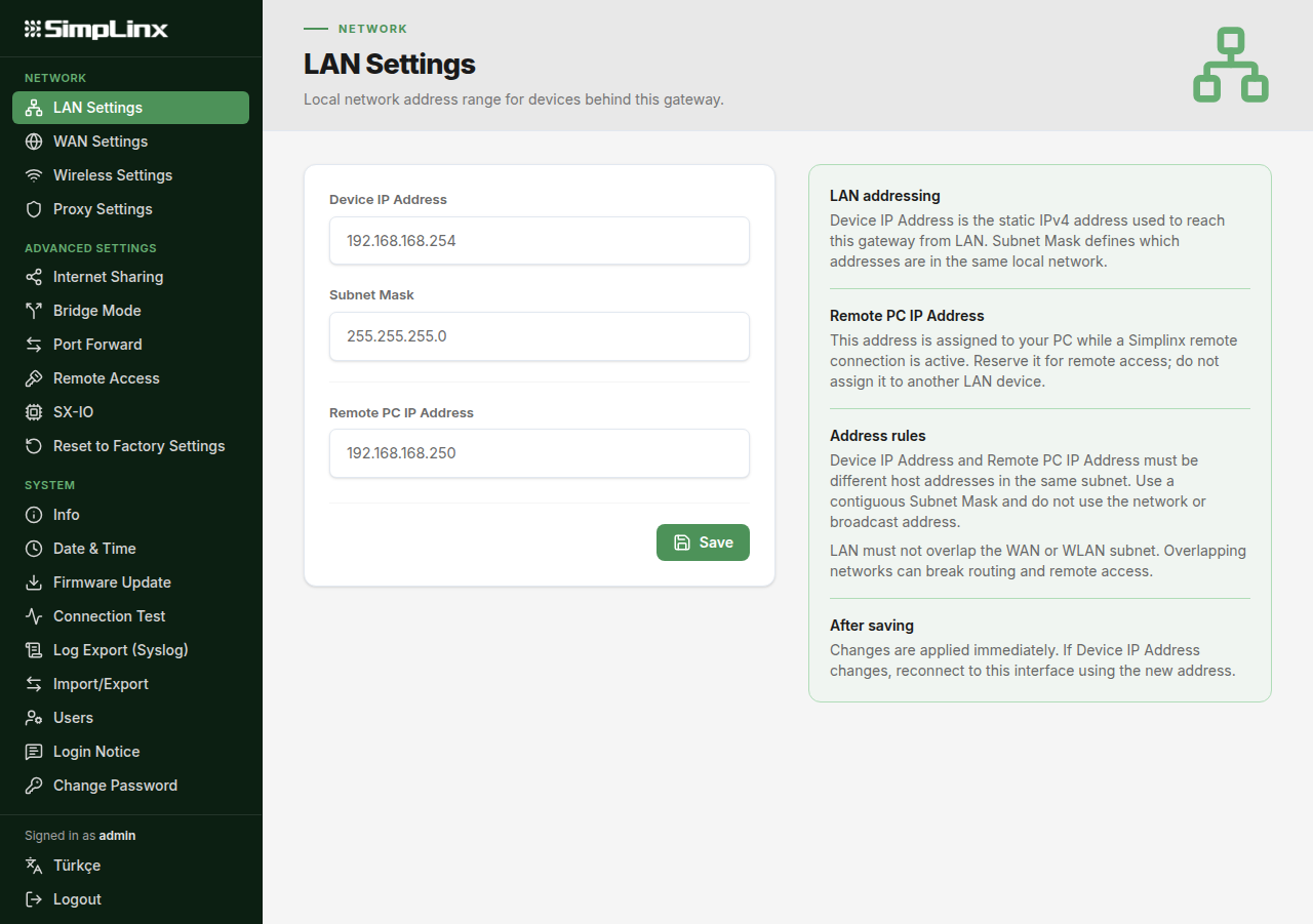
- Example (Predefined)
-
IP: 192.168.168.254
-
Subnet Mask: 255.255.255.0
-
IP (PC): 192.168.168.250
-
In this case, you can assign all IP addresses in the range [192.168.168.1 – 192.168.168.249 ] and [192.168.168.251 - 192.168.168.253] for your field devices.
WAN Settings Page
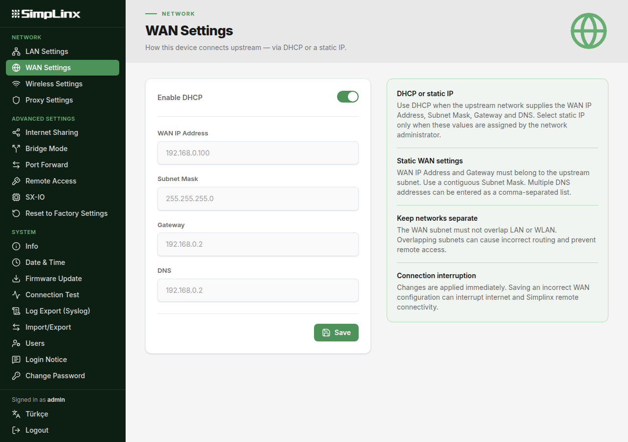
Section titled “WAN Settings Page”There are two options for WAN connection;
-
With DHCP, the device receives all configuration(Including IP address) (Recommended)
-
If you turn off DHCP, you can provide IP, Network Mask, Gateway and DNS configurations manually.
Wireless Settings Page
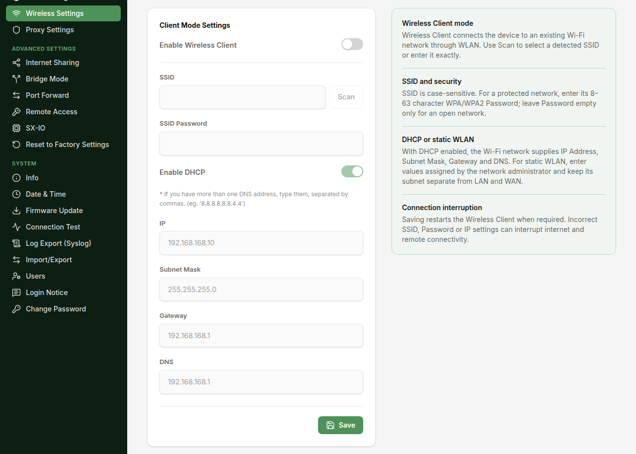
Section titled “Wireless Settings Page”You can access Wireless Client and Wireless Hotspot settings from this page.
Bu using the Wireless Client setting, you can connect your device to a wireless network and take your device online. There are two options;
-
You must select the wireless and DHCP options as active and enter the SSID, SSID Password information for the network you want to connect to.
-
If you turn off DHCP, you can provide network configuration manually by entering the IP, Network Mask, Gateway and DNS in addition to SSID and SSID Password information.
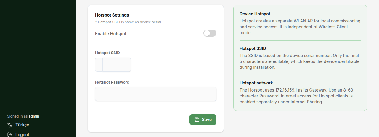
For wireless Hotspot connection;
- With the Wireless Hotspot setting, you can enable your device to broadcast Wi-Fi. By checking the “Hotspot Active” option and entering your Hotspot Password you want to set, you can enable your device to broadcast Wi-Fi with its serial number.
Proxy Settings
Section titled “Proxy Settings”For a proxy connection;
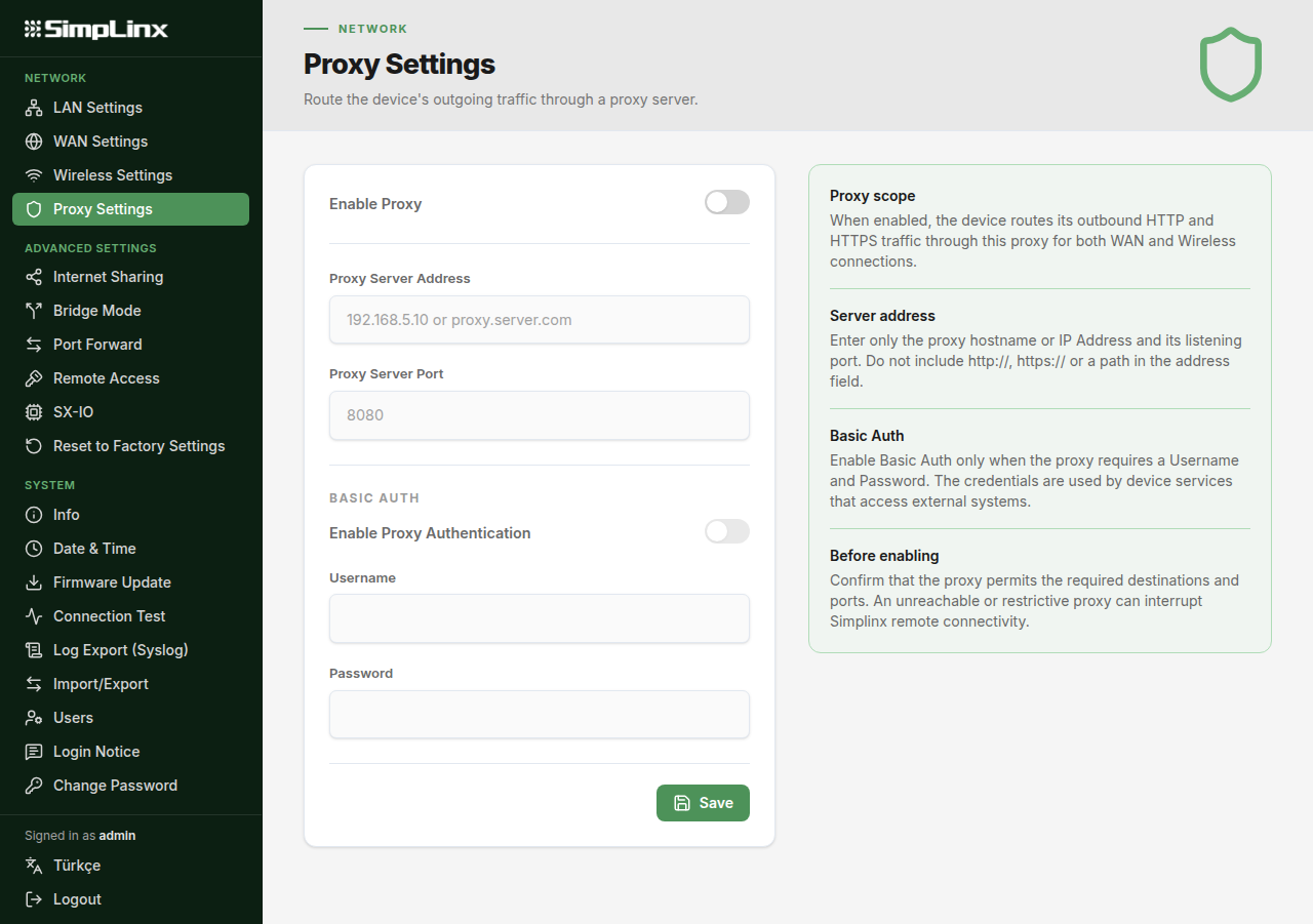
- To use proxy, you must enter the Proxy Server Address and port number. If you need Proxy Server user login, you can enter your username and password in the relevant field.
As an example, you can use these values;
-
Proxy Server Address: 192.168.5.10 or proxy.server.com
-
Proxy Server Port: 8080
-
User Name: (Proxy Server User Name)
-
Password: (Your Password)
Advanced Settings Page
Section titled “Advanced Settings Page”Advanced Settings holds Internet Sharing, Bridge Mode, Port Forward, Remote Access, SX-IO and Reset to Factory Settings. Port Forward, Remote Access and SX-IO have their own sections below.
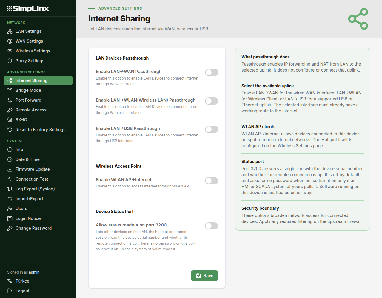
There are 3 options for Internet Sharing;
-
By checking the LAN-> WAN pass-through permission option, you can distribute the internet connection coming from the WAN to your devices in the LAN and enable your devices in the LAN to access the internet.
-
By checking the LAN-> WLAN pass-through permission option, you can distribute the internet connection coming from the WLAN to your devices in the LAN and enable your devices in the LAN to access the internet.
-
By checking the LAN-> USB pass-through permission option, you can distribute the internet connection coming from the USB (Phone) to your devices in the LAN and enable your devices in the LAN to access the internet.
After activating the internet sharing option you want to use;
-
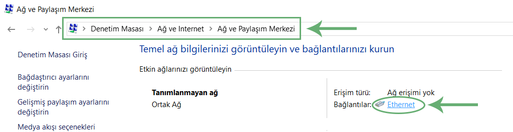
Go to “Control Panel” on the PC (Or Devices on LAN)
-
Go to the “Network and Internet” > “Network and Sharing Center” page and click on the “Links”
-
Press the “Properties” button in the pop-up window
-
Select TCP/IPv4 and press the “Properties” button again
-
Use the following IP address: select and specify the values as follows
-
IP Address: It must be in the LAN IP block of your SMX-RNS20 module.
-
Subnet Mask: Must be the same as the LAN MASK of your SMX-RNS20 module.
-
Default Gateway: Must be the LAN IP of your SMX-RNS20 module.
-
Preferred DNS Server: Must be the LAN IP of your SMX-RNS20 module.
-
Press the “OK” button.
-
You can close other remaining windows by pressing the “OK” button.
Bridge WAN & LAN Port
- In the Bridge WAN&LAN Port setting, enter the IP address of the device you want to create a bridge.
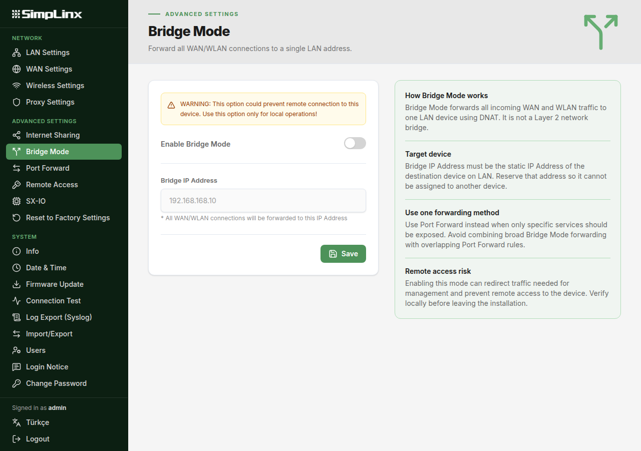
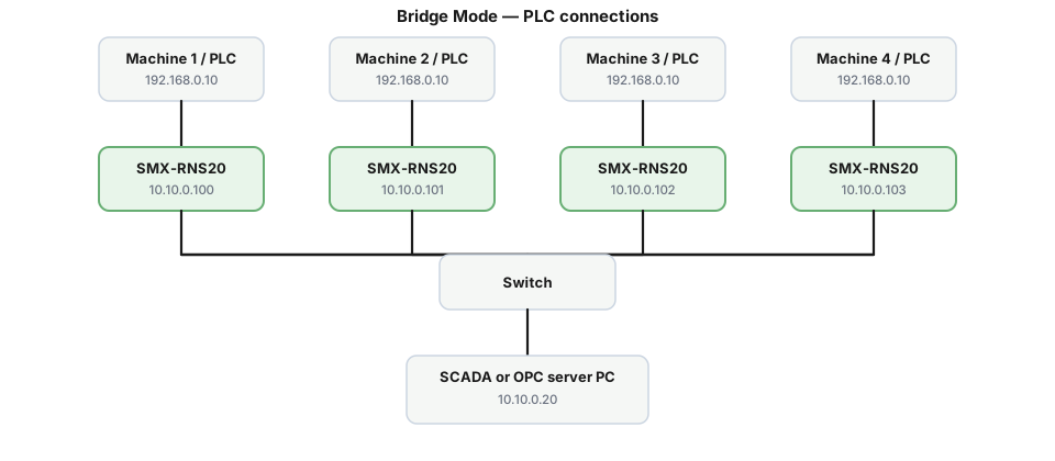
- Turn off the “DCHP” option from the WAN settings page and enter the IP address, Mask and Gateway values. Example above;
-
IP addresses: 10.10.0.100 - 101 - 102 - 103
-
MASK address: 255.255.255.0
-
Gateway address: 10.10.0.1
-
DNS address: 10.10.0.1
- For Example; after activating Bridge Mode all connections you send to the IP address “10.10.0.100” via PC will be transferred to PLC with the address “192.168.0.10” in the image above.
Reset to Factory Settings
-
SX-IO admin password. Choose a new SX-IO admin password here; it replaces the one SX-IO is using. There is no factory password to return to — you sign in to SX-IO as
adminwith the password you set. The change takes effect immediately; SX-IO does not restart. -
Reset device settings. Returns the device’s own settings to their factory state.
-
Reset the SX-IO database. Deletes the SX-IO database. SX-IO restarts to complete the process and is available again shortly.
Port Forward
Section titled “Port Forward”Expose LAN services by mapping WAN ports to internal addresses. Up to 8 records can be created.
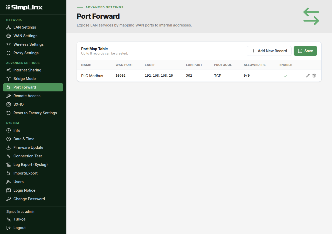
| Column | What it is |
|---|---|
| Name | A label for the record |
| WAN Port | The port opened on the WAN side. It must be above 1000, and it may not be one of the ports the device uses for itself — the page refuses one that is |
| LAN IP | The address on the LAN the connection is sent to |
| LAN Port | The port on that device |
| Protocol | TCP or UDP |
| Allowed IPs | Which source addresses may use the forward. 0/0 is any address |
| Enable | Whether the record is in effect |
Remote Access
Section titled “Remote Access”Remote access to the device can be gated by a key switch or a contact wired to the digital input: while the input has no voltage, remote access is blocked and an open session is ended.
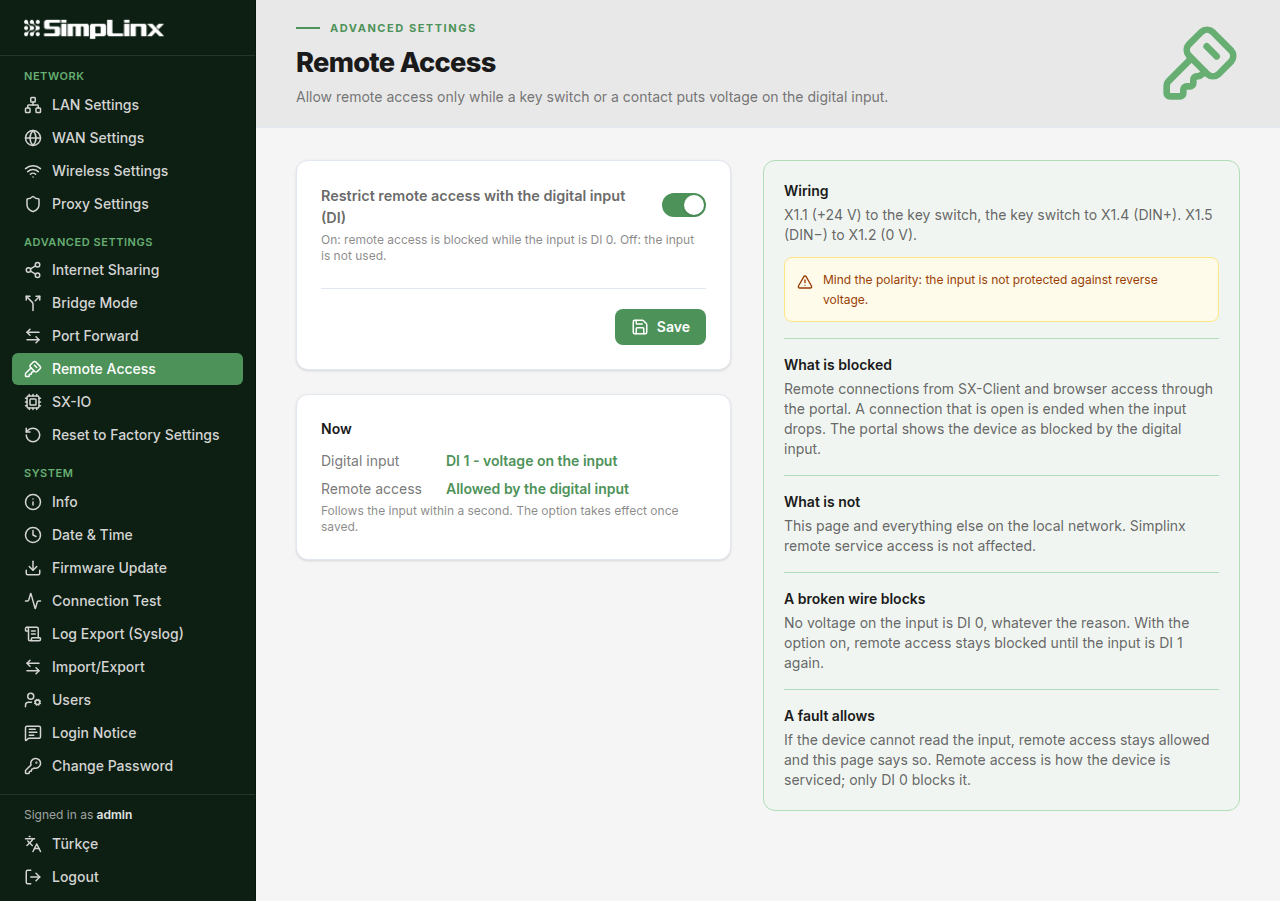
The option is off when the device leaves the factory. The Now box on the page shows the live state of the input, so the wiring can be checked before the option is turned on.
The wiring, the behaviour in every case and what to check when it does not work are in Remote access with a key switch.
SX-IO is the IO gateway that can run on this device. This page starts it and decides who may reach it.
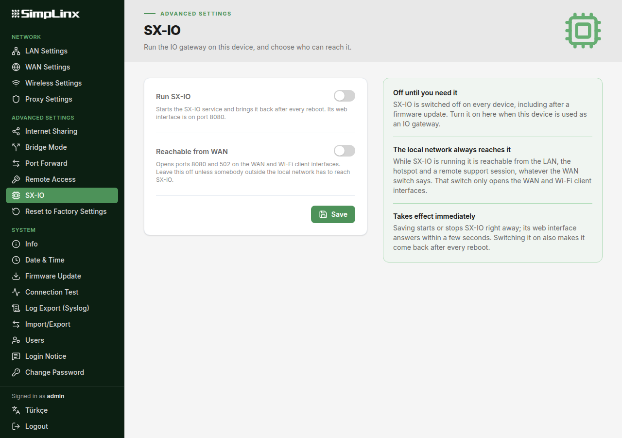
- Run SX-IO — starts the SX-IO service and brings it back after every reboot. Its web interface is on port 8080.
- Reachable from WAN — opens ports 8080 and 502 on the WAN and Wi-Fi client interfaces. Leave this off unless somebody outside the local network has to reach SX-IO.
SX-IO is switched off on every device, including after a firmware update; turn it on here when the device is used as an IO gateway. While it is running it is reachable from the LAN, the hotspot and a remote support session whatever the WAN switch says — that switch only opens the WAN and Wi-Fi client interfaces.
SX-IO has no admin password until you choose one. Switching it on asks for it, and you sign in to SX-IO as admin with it.
Saving starts or stops SX-IO right away; its web interface answers within a few seconds.
Import/Export Page
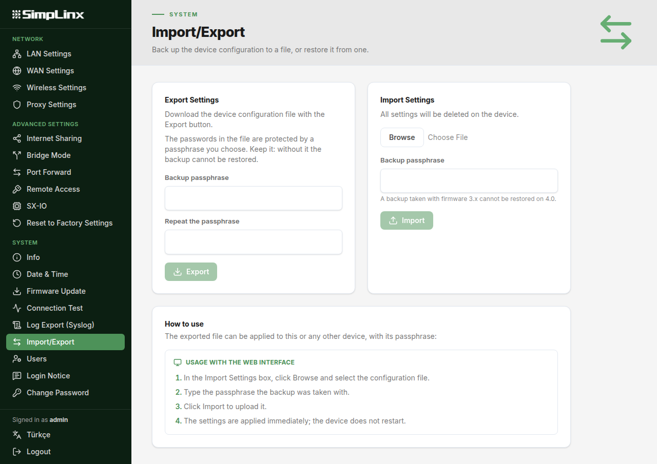
Section titled “Import/Export Page”On the Import/Export page you can back the device configuration up to a file, or restore it from one.
Export. Choose a backup passphrase and click Export; the browser downloads the configuration file. The passwords in the file are protected by that passphrase — keep it, because without it the backup cannot be restored. The file can be applied to this device or to any other device, with its passphrase.
Import. In the Import Settings box, click Browse and select the configuration file, type the passphrase it was taken with, and click Import. The settings are applied immediately; the device does not restart.
Change Password Page
Section titled “Change Password Page”On the Change Password page, you can change the password you use to sign in to the device’s configuration pages. This changes the password of the account you are signed in with; it does not change the Wi-Fi, Proxy or SX-IO credentials. For any other account, the administrator sets a new one from the Users page.
Info Page
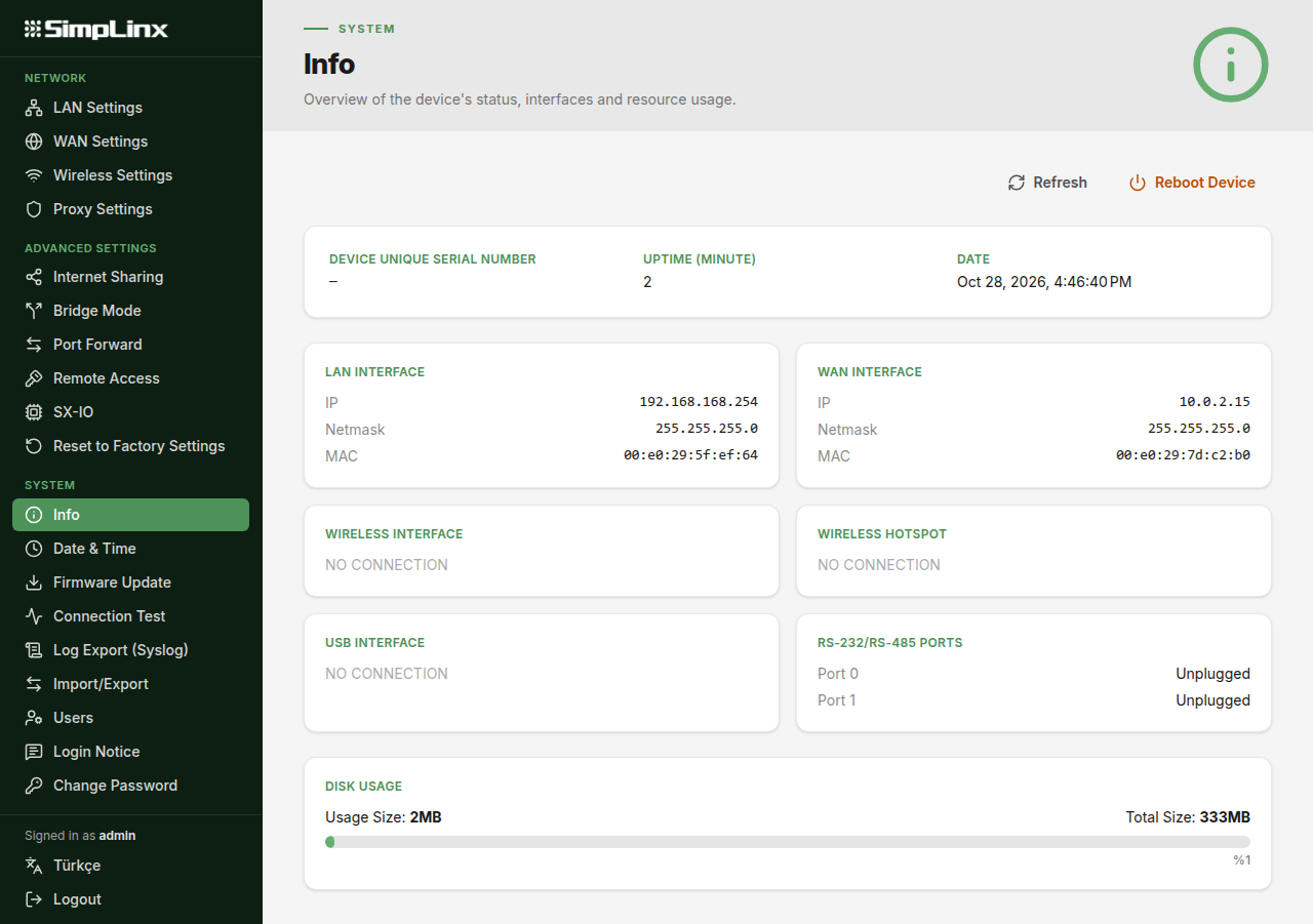
Section titled “Info Page”You can view the following information on the status page and you can reboot the device;
-
Serial Number of Your Device
-
Up Time (in Minutes)
-
Date and Time information of your device
-
IP, MASK and MAC information of the LAN interface
-
IP, MASK and MAC information of the WAN interface
-
If the WLAN is plugged in and connected to a network, IP, MASK and MAC information of the interface
-
If the WLAN Hotspot is connected and broadcasting, the IP, MASK and MAC information of the interface
Date & Time
Section titled “Date & Time”Keep the clock on a time server, or set it by hand.
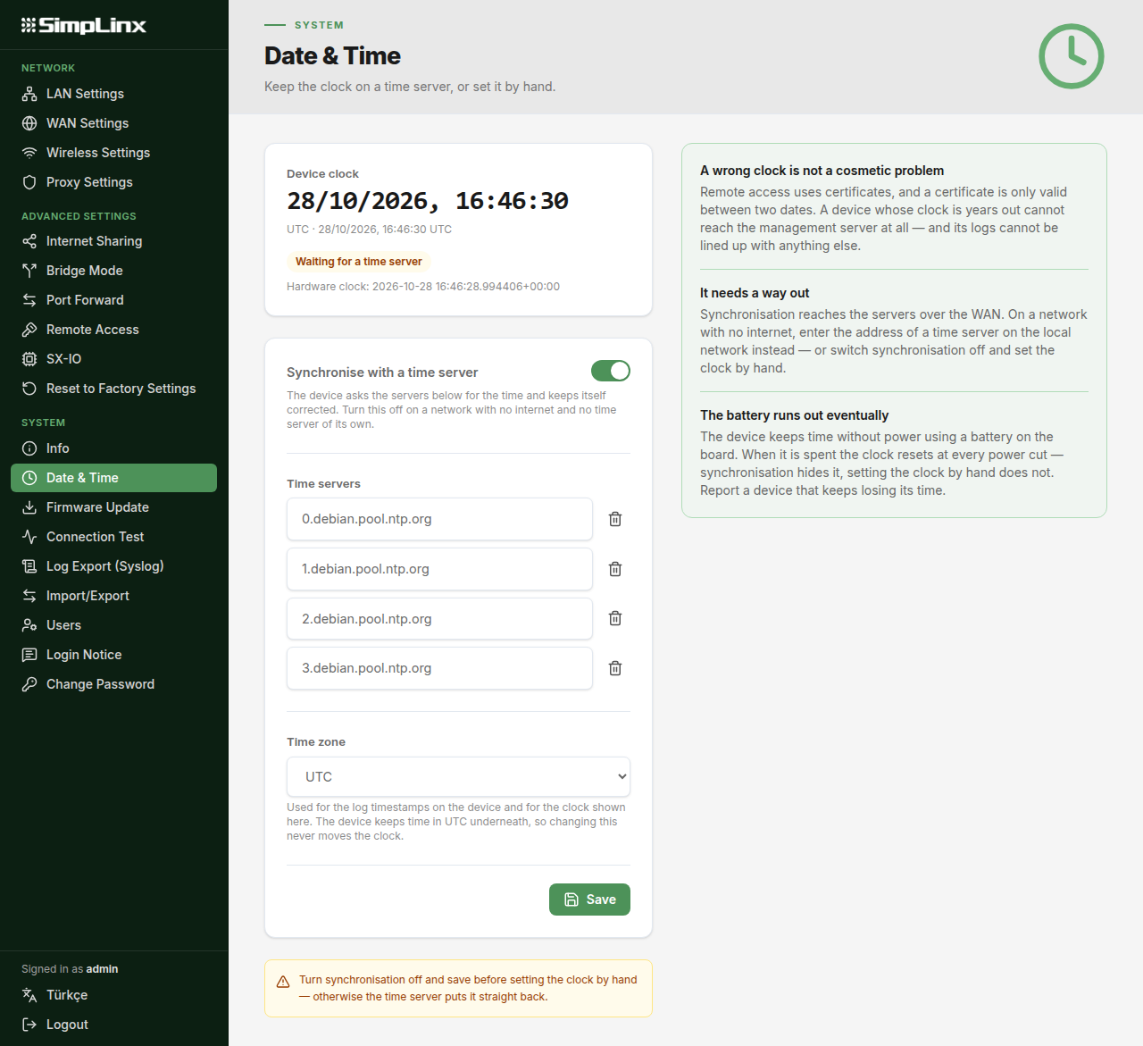
- Synchronise with a time server — the device asks the servers listed for the time and keeps itself corrected. Turn it off on a network with no internet and no time server of its own.
- Time zone — used for the log timestamps on the device and for the clock shown on this page. The device keeps time in UTC underneath, so changing the zone never moves the clock.
- Set the clock — enter the time as it is where the device stands. It is written to the hardware clock, so it survives a power cut. Turn synchronisation off and save first, otherwise the time server puts the old time straight back.
Firmware Update
Section titled “Firmware Update”Check for updates, or update the device from a file.
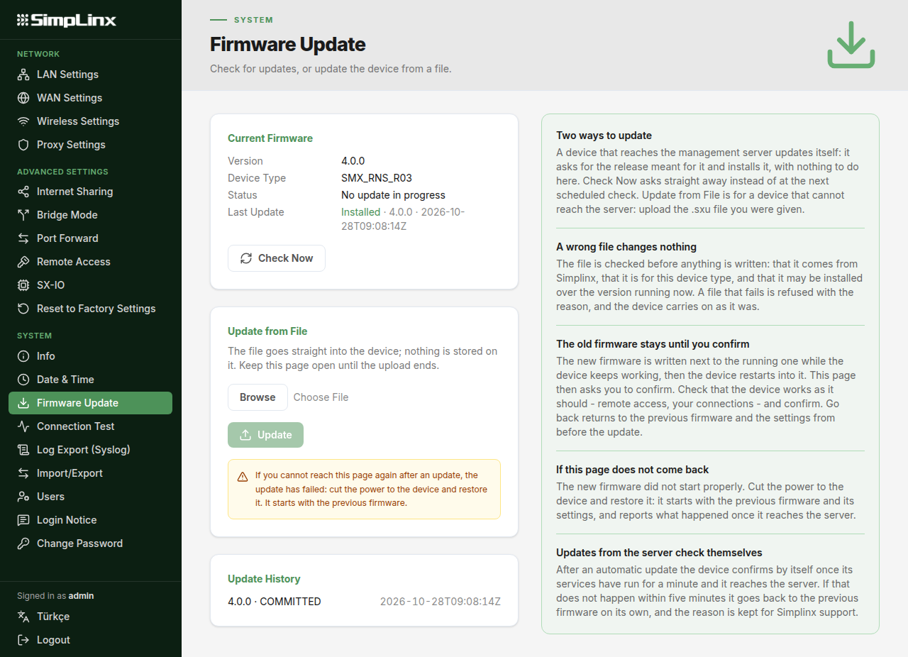
The page shows the firmware the device is running, its device type and how the last update ended. Check Now asks for a newer release. Update from File takes a release file from your PC — the file goes straight into the device and nothing is stored on it, so keep the page open until the upload ends.
Connection Test
Section titled “Connection Test”Checks this device’s connectivity to the Simplinx service and to the internet. Run it when a device will not come online; it reports where the connection stops.
Log Export (Syslog)
Section titled “Log Export (Syslog)”Forwards the device log — or only its audit record — to your own syslog or SIEM server. Off by default: nothing leaves the device until it is turned on and a server is named.
How to set it up, what each scope sends and the list of audit events are in Exporting the log to a syslog server.
Who else may sign in, and what each account may change.
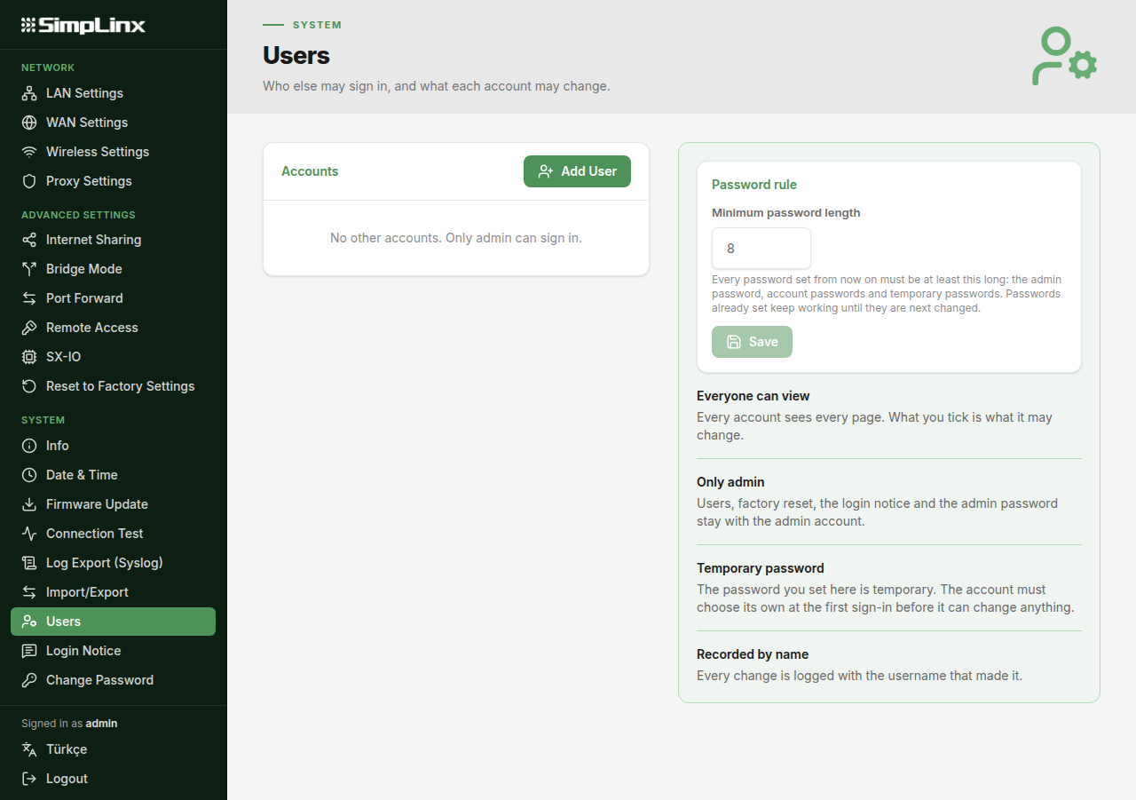
Every account sees every page; what you tick for an account is what it may change. Users, factory reset, the login notice and the admin password stay with the admin account.
The password you set for a new account is temporary: the account has to choose its own at the first sign-in before it can change anything. Every change is recorded with the username that made it.
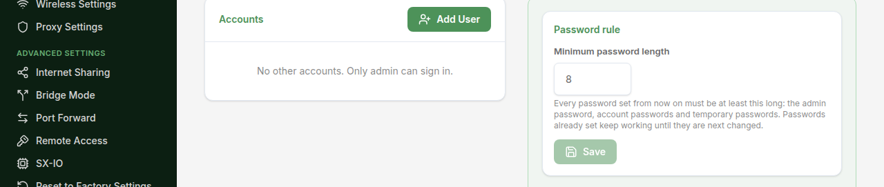
The minimum password length for the device is set on the same page.
Login Notice
Section titled “Login Notice”The text shown before anyone signs in — above the sign-in form of this interface, and in an SSH session before the password is asked for.
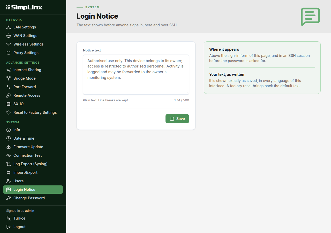
Plain text, and line breaks are kept. It is shown exactly as saved, in every language of the interface. A factory reset brings back the default text.
Accessories
Section titled “Accessories”Installation of the SMX-N1559 USB WiFi Module
Section titled “Installation of the SMX-N1559 USB WiFi Module”-
Place and tighten the antenna if it is un-mounted.
-
Plug the USB Wi-Fi module into an empty USB slot of the SMX-RNS20.
-
Your SMX-N1559 module is ready for use.
See the relevant documentation for detailed information.
SMX-RS001 Connection
Section titled “SMX-RS001 Connection”-
Plug the SMX-RS001 cable into an empty USB slot of the SMX-RNS20.
-
Plug other side of the SMX-RS001 cable to the device you want to connect to.
-
SMX-RS001 cable is ready for use.
See the relevant documents for detailed information and electrical drawings.
07/2020 man-en-smx-rns02.docx Version 1.3 |
SimpLinx Elektronik Ltd. Halil Rifat Pasa Mh. Nazli Sk. No:1/5 No:17 Sisli/Istanbul www.simplinx.com |
|---|
Change Log
Section titled “Change Log”| Version | Date | Description |
|---|---|---|
| V1.0 | 07/2020 | Draft |
| V1.1 | 07/2020 | Typos |
| V1.2 | 07/2020 | Typos |
| V1.3 | 01/2021 | New Features |
| V1.4 | 12/2025 | Power |
| V1.5 | 10/2026 | Firmware 4.0: the web interface sections rewritten and the new pages added; settings apply without a restart; a backup is sealed with a passphrase and import from a USB disk is gone |
Legal Notices
Section titled “Legal Notices”Warning Notice System
Section titled “Warning Notice System”The document contains alerts and information indications for the safety of you and your devices. The symbols and meanings used to draw your attention to these notifications are listed below.
Qualified Personnel
Section titled “Qualified Personnel”It is assumed that what is described in this document will be applied by qualified personnel for the specific task.
Disclaimer
Section titled “Disclaimer”We have reviewed the contents of this publication to ensure consistency with the hardware and software described. Since variance cannot be precluded entirely, we cannot guarantee full consistency. The information in this publication is reviewed regularly and any necessary corrections are included in subsequent editions.